
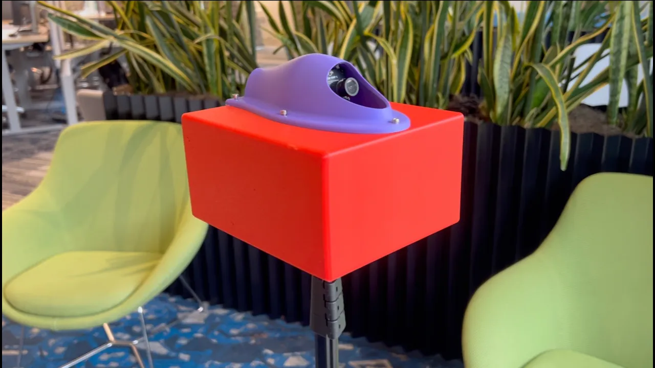
Solo Build · 48 Hours · ~$150 · SolidWorks · Embedded Systems · Jetson Orin Nano · Python · GNSS · FDM Printing
Self-Run, <48 Hour Buildathon
I found Zipline's Mechatronics Perception internship posting on a Friday afternoon. It asked for someone who could take a prototype data collection rig from CAD through embedded software and out into the field.
I've spent the past year year building IoT sensors — acoustic sensing on pipes, fill-level sensing in dumpsters. Same shape of problem, pointed at the ground instead of the sky.
Instead of submitting a blind application just claiming I had the passion and capability, I gave myself the weekend to build an MVP as proof.
The following weekend, I had an idea on how to vastly improve upon my design, so keep reading to the end to see the second version. The second version uses a long focal-length camera mounted on a servo for 4.1x longer range object detection!
Understanding The Constraints
Zipline's aircraft fly BVLOS, over populated areas, thousands of times a day. This demands reliable object detection & avoidance. The difficult part is sensing non-cooperative traffic — a small plane with no transponder, the glider, the drone broadcasting no signals. Before designing the enclosure, I compared five sensing approaches based on range, weight, power, weather sensitivity, integration difficulty, and available training data.
mmWave radar: Useful in larger architectures, but affordable evaluation boards did not provide enough range to justify the cost and integration effort for this MVP.
LiDAR: Precise at shorter ranges, but less attractive for small airborne targets and degraded-weather operation.
ADS-B: Lightweight and long-range, but limited to cooperative aircraft that broadcast their position.
Acoustic sensing: Valuable, but not the most differentiated experiment for this prototype. I knew Zips already had great acoustic sensing abilities built by the Zipline team.
Vision: Passive, lightweight, high-resolution, and supported by public airborne-object datasets.
I selected vision because it offered the strongest detection potential within a weekend budget. If given more time and resources I would experiment with airborne-grade radars from companies like EchoDyne.
The design intention behind my two-part system was to have a aerodynamic component that could be bolted directly onto the drone, while also being able to easily attach to a larger rig for ground-based testing. While testing the aerodynamic pod, I would improve on the reliability, data quality, and functionality of each sensor.
I made an educated guess that the data collected would be used to train deep learning models on object detection and avoidance. This is why I included a GNSS sensor; it will time stamp each camera frame on UTC which will preserve data quality and allow for future auto-labeling of aircraft detected through an onboard ADS-B sensor.

Mechanical Design Process
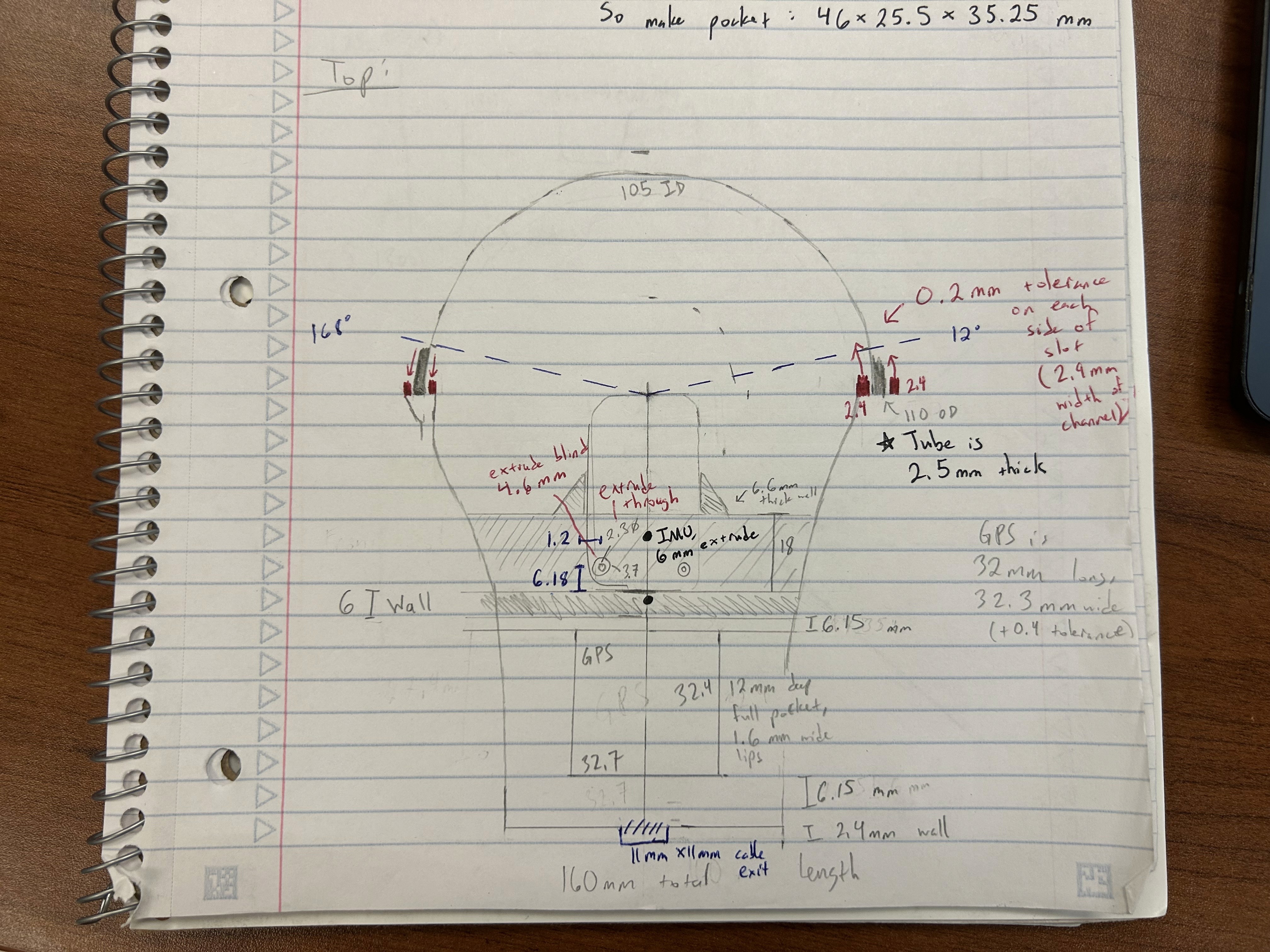
I modeled the enclosure in Onshape around the camera and GNSS hardware rather than forcing the electronics into a predetermined shell.
Using a 3:1 fineness ratio (length:width), in the range used for low-drag bodies of revolution, the internal packaging back-solved to a pod measuring approximately 58 × 48 × 158 mm. I used an elliptical nose and truncated Kamm tail to create an aerodynamic profile.
The camera sits 15° above horizontal on four silicone vibration isolators. A flat optical window remains normal to the lens axis, reducing refractive distortion and preserving a repeatable relationship between the camera and enclosure.
These features are not cosmetic. Camera movement, vibration, and optical distortion directly affect the quality of the collected data. As I learned from my robotic arm build, biased data can quickly distort what would otherwise be high quality training data.
Improving V1
During this build, I questioned whether my camera module would truly be able to detect small objects at the distance required for the aircraft to course correct. I used the 2.8mm focal length to calculate that an 11-meter Cessna at 1.5 kilometers would occupy only about six pixels with the wide-angle lens. This is far beneath the precision needed.
Working backwards to the necessary camera focal length, I found that switching to a 12 mm M12 lens increased that estimate to roughly 25 pixels while requiring a much narrower window. This led me to ideate a better perception architecture explained below!
Rebuilding V2 Around Resolution
The core problem with V1 was geometric. A wide-angle lens spreads the same number of pixels across a much larger portion of the sky, so a distant aircraft occupies too few pixels to classify.
V2 solves this by switching to a 12mm lens, which concentrates the same sensor pixels over a narrower slice of sky and resolves objects at 4.1× the distance. The tradeoff is that a narrow lens only sees about 24° at a time, and I need 180° of coverage ahead of the aircraft.
So I mounted the camera on a servo to scan the sky in increments. Nine positions, 19.5° apart, stepping at 5 Hz, with overlap between frames so part of the sky falls through the gaps. This buys resolution at the cost of revisit time — in the worst case, a patch of sky at the edge of the sweep goes 3.2 seconds between looks. That penalty is real and I sized the system around it rather than hiding it.
This matters more than raw pixel count suggests. Convolutional networks compress images through successive pooling and striding layers, and small objects lose their distinguishing features in that compression — the fine detail that separates an aircraft from a bird gets averaged away before the network ever evaluates it. Putting more pixels on the target means those features survive deep enough into the network to be usable.
For production I’d move from the hobby-grade servo to a brushless motor. Brushed motors wear at the commutator, and a scanning payload running continuously across a fleet accumulates cycles fast. A brushless motor with a proper field-oriented controller removes that wear item entirely and gives finer position control.
Designing with Model Training In Mind
A camera that captures good images is not the same as a rig that produces good training data. Every frame needs to be answerable to the question: where in the sky was this looking?
Three sensors allow me to calculate that. A GNSS module gives the pod’s position on Earth. The servo’s encoder reports exactly where the camera was pointing relative to the aircraft. An IMU reports how the aircraft itself was oriented — pitch, roll, and yaw. Chained together, those three let you convert a detection in an image into a real-world direction.
Every frame is stamped with UTC time from the GNSS receiver. Onboard clocks drift and reset; GNSS time is disciplined by atomic clocks in orbit. That matters because it makes data from separate aircraft, directly comparable on one timeline.
Images are written as PNG files on disk, with every frame’s metadata — timestamp, position, attitude, servo angle — logged to Parquet, the columnar format standard in large-scale machine learning pipelines. I chose it over a simpler format because a dataset this will eventually grow into needs to be filtered by scan angle or location without loading everything into memory.
I also chose to capture discrete frames rather than continuous video. Video would write thirty times more data, most of it captured mid-motion and unusable. Discrete capture ties every image to a known servo position by construction.
Manufacturability and Future Direction
V1 worked but was awkward to assemble. V2 was designed to be fabricated en masse.
Now, everything now assembles from a single direction. The shell has a flat closed bottom and a separate top cover, so the servo, camera bracket, GNSS module, and IMU all drop in from above. I also considered maintenance cycles- using threaded brass inserts rather than screwing fasteners directly into printed threads, so the pod survives being taken apart repeatedly.
It’s important to note that the camera’s scanning defined the geometry in this version. I designed for a cylindrical window in front, with the camera’s rotation axis running down its center, so the camera always looks through the window perpendicularly regardless of direction. I accepted the aerodynamic cost, but would like to use airflow simulations to determine empirically whether this added drag is actually significant.
The next work is on the shape itself. My current aerodynamic reasoning uses analytical estimates and published form-factor correlations, which are reasonable for a first pass but can’t capture how the flow actually behaves at the window transition or where separation begins on the aft body. I would like to run proper airflow simulation and review the geometry with an aerospace engineer.
Beyond that: making the pod fully self-contained on embedded compute powered from the aircraft bus, moving from an SD card to NVMe storage, and logging IMU data continuously rather than once per frame. Continuous attitude data is what enables the frame-to-frame alignment that lets detection algorithms integrate a target across multiple looks — which is how the best published systems find aircraft only a handful of pixels across.
I had a fun time building this device and hope to bring this initiative and energy to Zipline this Fall!