The Inspiration
Historically, machines could only execute a precise set of commands. Every situation it might encounter had to be anticipated in advance by whoever wrote the code. I believe the trillions of dollars of value created by traditional, deterministic robots will pale in comparison to the new era of machines that have intelligent judgement (neural nets). This is what inspired me to search for a robotics project that would allow me to get a true understanding of each part of the tech stack that powers probabilistic machines.
Ultimately, this project taught me that the neural network that determines the autonomy of a robot depends on every layer in the stack beneath it. Reliable behavior depends just as much on mechanical calibration, power delivery, camera geometry, communication timing, data quality, and disciplined testing.
Building the Mechatronic System
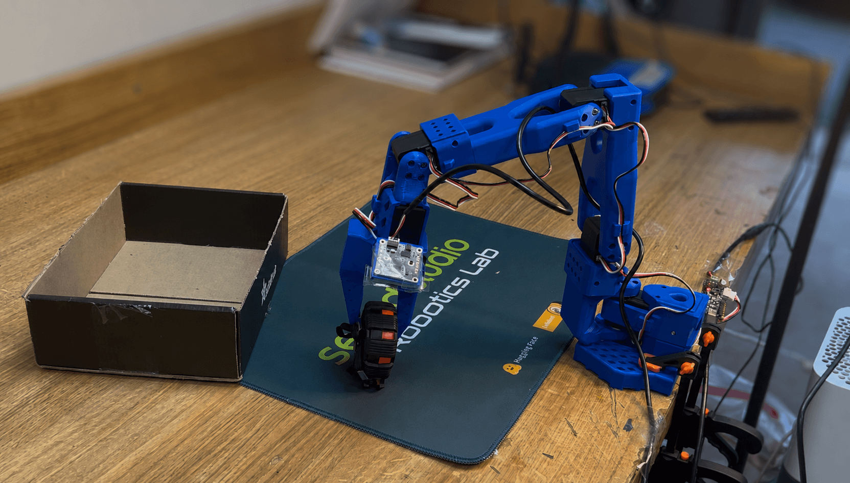
The SO-101 is an open-source leader–follower platform consisting of two six-degree-of-freedom arms and 12 Feetech STS3215 smart servos. I got to skip the mechanical design work, but learned the best lessons through integrating each component: assembly, power architecture, motor configuration, calibration, sensing, data collection, policy training, edge deployment, and hardware debugging.
The two arms serve different purposes.
The leader arm is moved by hand during teleoperation. Its 7.4 V servos are backdrivable enough for me to demonstrate the task naturally. The follower arm reproduces those joint positions using 12 V servos with 1:345 gearing, providing the torque needed to manipulate the object.
Each arm’s six servos was assigned an ID from 1 through 6. The motors communicate over a shared half-duplex serial bus: the computer transmits commands, then yields the data line so the servos can return their positions and status. Because communication happens sequentially, bus timing directly affects how quickly the robot can observe and respond.
I added two USB cameras with complementary viewpoints. A wrist camera provided a close view of the gripper and object, while an overhead camera supplied broader scene context, including the target box. I used a Mac for teleoperation and initial testing, a cloud GPU for training, and an NVIDIA Jetson Orin Nano to host the final policy and run experiments.
Calibration Constrained Data Quality
Before collecting data, I calibrated the encoder offsets and allowable joint ranges on both arms so that a pose on the leader corresponded to the same physical pose on the follower. This established the coordinate relationship underlying every demonstration.
Power introduced a different integration failure. The leader’s 7.4 V servos were accidentally connected to the follower’s 12 V supply, causing the entire leader arm to stop returning status packets. The symptom initially resembled a serial communication failure, but the cause was electrical.
After separating the power rails, I tested each affected servo individually for correct identification, temperature, motion, and calibration before returning the system to operation. That failure reinforced an important mechatronics principle: the subsystem reporting the error is not necessarily the subsystem causing it.
Demonstrations To Training Data
I recorded 117 variations of the tape-measure pick-and-place task. Each episode contained timestamped wrist and overhead video, follower joint states, commanded actions, and episode metadata.
Camera streams were stored as MP4 files, while joint states and actions were saved as structured Parquet data with normalization metadata. I then uploaded the dataset to the Hugging Face Hub for training through the LeRobot ecosystem.
Synchronization was critical. The model’s training signal is fundamentally: Given this image and this robot state, what action should happen next?
I also had to balance diversity with consistency. I varied the tape measure’s position and orientation so the robot could not memorize one trajectory. At the same time, my demonstrations needed a consistent strategy. Hesitation, unnecessary corrections, and failed grasps could all become behaviors the model attempted to reproduce.
Action Chucking Transformer (ACT) Policy
I trained an Action Chunking Transformer, or ACT, for 100,000 steps.
ACT receives the camera observations and current joint state, then predicts a short sequence—or chunk—of future joint actions. This helps the policy represent coordinated movements such as closing the gripper while beginning to lift, rather than treating every motor command as an independent decision.
Predicting short action sequences can also produce smoother behavior and reduce the accumulation of small errors between individual control steps.
A decreasing training loss showed that the model was fitting the demonstrations. It did not prove that the robot could complete the task. That required closed-loop testing on physical hardware, where every predicted action changed the scene the model observed next.
Discovering Compute Bottlenecks
During physical rollouts, the control loop would begin near 30 Hz and quickly fell to 9 Hz. In a separate diagnostic condition, USB contention reduced the loop from roughly 60 Hz to 1 Hz while camera frames became more than 600 milliseconds old.
At that point, the policy was making decisions about a scene that no longer existed. Commands arrived late, motion became jerky, and positioning errors grew faster than the robot could correct them.
I treated the robot as an end-to-end timing system: Camera capture → USB transfer → image preprocessing → neural-network inference → action generation → serial communication → servo response.
Any stage could constrain the entire loop. Rather than assuming the model was too slow, I measured loop frequency and frame age, isolated USB devices across different ports and hubs, reduced camera resolution and frame rate, and tested camera acquisition, inference, and motor communication independently. I used Rerun visualization to compare the observations received by the policy with the actions it commanded, and repeated deployment tests on both Apple Silicon and my Jetson Orin Nano Dev Kit.

Importance of Root-Cause Analysis
During some policy rollouts, repeated wrist-roll commands also caused the joint to overheat, despite the same motor functioning properly during manual teleoperation.
Potential mechanisms included calibration error, repeated oscillatory commands, joint-limit behavior, or a motion pattern learned from the demonstrations. I conducted a series of tests to isolate possible root-causes, ultimately determining the motor was mis-calibrated which caused the ACT policy to command positions that strained the motor beyond its mechanical limit.
This taught me how to best investigate hardware failures in projects with many electromechanical subsystems: document the symptom, generate plausible mechanisms, design tests that separate them, and avoid declaring a cause before the evidence supports it.
What Comes Next
The robot demonstrated reliable placement and release once it achieved a secure grasp. Initial grasping remained inconsistent because of observation geometry and control-loop performance.
The next iteration will move the overhead camera forward to reduce self-occlusion, add RGB-D sensing for depth, improve the compute and camera pipeline, and evaluate performance systematically across controlled object positions. I would measure success separately for approach, grasp, transport, and release so each failure can be traced to the stage that produced it.
This project changed my understanding of embodied AI. The bottleneck to reliable autonomy was not simply model architecture or training dataset size. Performance depended on calibrated joints, correct power, observable geometry, synchronized demonstrations, fresh camera frames, adequate compute, healthy serial communication, and tests designed to distinguish one failure mechanism from another.
The policy learned the behavior, but the quality of the entire mechatronic system determined whether that behavior survived contact with the physical world.